Relay
The relay is an electromechanical device, which transforms an electrical signal into mechanical movement. It consists of a coil of insulated wire on a metal core, and a metal armature with one or more contacts. When a supply voltage was delivered to the coil, current would flow and a magnetic field would be produced that moves the armature to close one set of contacts and/or open another set. When power is removed from the relay, the magnetic flux in the coil collapses and produces a fairly high voltage in the opposite direction. This voltage can damage the driver transistor and thus a reverse-biased diode is connected across the coil to "short-out" the spike when it occurs.

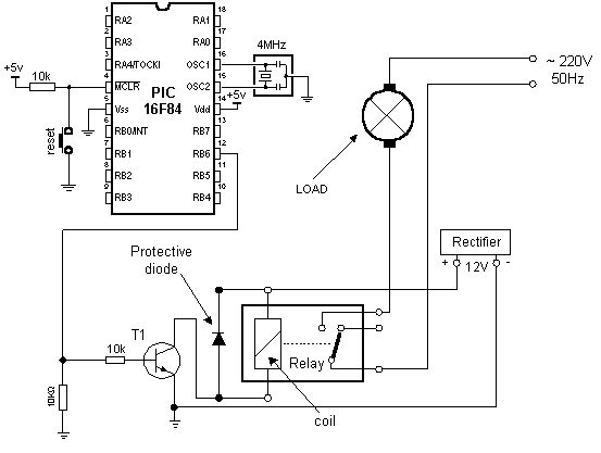
Connecting a relay to the microcontroller via transistor
Since microcontroller cannot provide sufficient supply for a relay coil
(approx. 100+mA is required; microcontroller pin can provide up to 25mA),
a transistor is used for adjustment purposes, its collector circuit
containing the relay coil. When a logical one is delivered to transistor
base, transistor activates the relay, which then, using its contacts,
connects other elements in the circuit. Purpose of the resistor at the
transistor base is to keep a logical zero on base to prevent the relay
from activating by mistake. This ensures that only a clean logical one on
RA3 activates the relay.

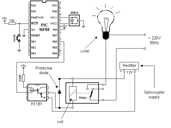
Connecting the optocoupler and relay to a microcontroller
A relay can also be activated via an optocoupler which at the same time amplifies the current related to the output of the microcontroller and provides a high degree of isolation. High current optocouplers usually contain a 'Darlington' output transistor to provide high output current.
Connecting via an optocoupler is recommended especially for microcontroller applications, where relays are used fro starting high power load, such as motors or heaters, whose voltage instability can put the microcontroller at risk. In our example, when LED is activated on some of the output port pins, the relay is started. Below is the program needed to activate the relay, and includes some of the already discussed macros.
        PROCESSOR   16F84
        #INCLUDE  "P16F84. INC"
__CONFIG _CP_0FF  &  _WDT_0FF  &  _PWRTE_0N  &  _XT_0SC


        CBLOCK 0X0C                    ;RAM starting address
        HICNT
        LOCNT
        LOOPCNT
        ENDC

#DEFINE RELAY PORTA,3               ;Relay is  located on  the  third pin ;of port A

        ORG 0X00                 ;Reset vector
        GOTO MAIN
        ORG 0X04                ;Intertupt vector
        GOTO MAIN                ;no  interrupt routine

        #INCLUDE "ROMUX_LIB.INC"
        #INCLUDE  "BUTTON.INC"

MAIN                            ;Beginning of  the program
            BANKSEL  TRISA
            MOVLW   B' 00010111';initializing port A
            IWVWF   TRISA       ;TRISA <-  0x17
            MOVLW   0X00       ;initializing port B
            MOVWF   TRISB         ;TRISB <-  0x00
            banksel   P0RTB
            CLRF      P0RTB     ;P0RTB <-  0x00
LOOP
            BUTTON    PORTA,   0,   0,   ON   ;Button  1
            BUTTON    PORTA,   1,   0,   OFF  ;Button  2
            GOTO      LOOP
ON        BSF RELAY               ;Turn on relay GOTO  Loop
OFF        BCF RELAY               ;Turn off  relay GOTO  Loop
        END                     ;END of program
User Comments
No Posts found !Login to Post a Comment.