Push buttons
Buttons are mechanical devices used to execute a break or make connection between two points. They come in different sizes and with different purposes. Buttons that are used here are also called "dip-buttons". They are soldered directly onto a printed board and are common in electronics. They have four pins (two for each contact) which give them mechanical stability.

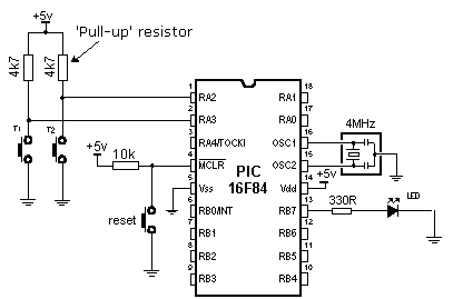
Example of connecting buttons to microcontroller pins
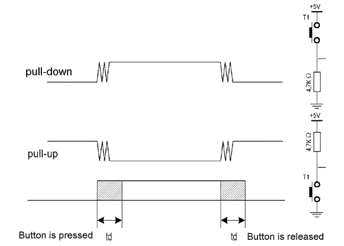
Button function is simple. When we push a button, two contacts are joined together and connection is made. Still, it isn't all that simple. The problem lies in the nature of voltage as an electrical dimension, and in the imperfection of mechanical contacts. That is to say, before contact is made or cut off, there is a short time period when vibration (oscillation) can occur as a result of unevenness of mechanical contacts, or as a result of the different speed in pushing a button (this depends on person who pushes the button). The term given to this phenomena is called SWITCH (CONTACT) DEBOUNCE. If this is overlooked when program is written, an error can occur, or the program can produce more than one output pulse for a single button push. In order to avoid this, we can introduce a small delay when we detect the closing of a contact. This will ensure that the push of a button is interpreted as a single pulse. The debounce delay is produced in software and the length of the delay depends on the button, and the purpose of the button. The problem can be partially solved by adding a capacitor across the button, but a well-designed program is a much-better answer. The program can be adjusted until false detection is completely eliminated. Image below shows what actually happens when button is pushed.

As buttons are very common element in electronics, it would be smart to have a macro for detecting the button is pushed. Macro will be called button. Button has several parameters that deserve additional explanation.
button macro port, pin, hilo,
label
Port is a microcontroller's port to which a button is connected. In case of a PIC16F84 microcontroller, it can be PORTA or PORTB.
Pin is port's pin to which the button is connected.
HiLo can be '0' or '1' which represents
the state when the button is pushed.
Label is a destination address for jump to a service subprogram
which will handle the event (button pushed).
BUTTON MACRO PORT,PIN,HILO,LABEL
        LOCAL PUSHEDL                    ;A11  labels  used are  local
        LOCAL PUSHED2
        LOCAL EXITL
        LOCAL EXIT2
IFNDEF DEBOUNCEDELAY                    ;This   enables  to  define  a  debounce
        #DEFINE  DEBOUNCEDELAY  .10        ;delay in  the main program
ENDIF

IF HILO==0                                ;pull-up
            IFBIT PORT,PIN,EXIT1         ;If  one,   button  is not pushed
            PAUSEMS   DEBOUNCEDELAY        ;10ms   deb ounce   delay
PUSHEDL
            IFNOTBIT PORT,PIN,PUSHEDL
            PAUSEMS   DEBOUNCEDELAY     ;Wait until   released and
            GOTO   LABEL                ;then  jump  to  a specified  label
EXIT1
ELSE                                    ;pull-down
            IFNOTBIT PORT,PIN,EXIT2     ;If  zero,   button is  not pushed
            PAUSEMS   DEBOUNCEDELAY        ;10ms   deb ounce   delay
PUSHED2
            IFBIT PORT,PIN,PUSHED2
            PAUSEMS   DEBOUNCEDELAY     ;Wait until   released and
            GOTO   LABEL                ;then  jump  to  a specified  label
EXIT2
ENDIF
ENDM
Example 1:
button PORTA, 3, 1, Button1
Button T1 is connected to pin RA3 and to the mass across a pull-down resistor, so it generates logical one upon push. When the button is released, program jumps to the label Button1.
Example 2:
button PORTA, 2, 0, Button2
Button T1 is connected to pin RA1 and to the mass across a pull-up resistor, so it generates logical zero upon push. When the button is released, program jumps to the label Button2.
The following example illustrates use of macro button in a program. Buttons are connected to the supply across pull-up resistors and connect to the mass when pushed. Variable cnt is displayed on port B LEDs; cnt is incremented by pushing the button RA0, and is decremented by pushing the button RA1.
            PROCESSOR  16f84
            #INCLUDE "P16F84. INC"
__CONFIG _CP_0FF   &  _WDT_0FF  &   _PWRTE_0N   &  _XT_0SC

            CBLOCK    0X0C        ;RAM  starting  address
            HICNT
            LOCNT
            LOOPCNT
            CNT
            ENDC

            ORG  0X00            ;Reset vector
             GOTO  MAIN


            ORG   0x04        ;Interrupt vector
            GOTO  MAIN        ;no   interrupt  routine

            INCLUDE    "ROMUX_LIB.INC"
            INCLUDE    "BUTTON.INC"

MAIN                    ;Main program
            INPUT PORTA,0
            INPUT PORTA,0
            BANKSEL TRISB
            CLRF TRISB
            BANKSEL PORTS
            CLRF CNT
LOOP
            BUTTON PORTA,0,0,DECREASE
            BUTTON PORTA,1,0,INCREASE
            GOTO LOOP
INCREASE
            INCF CNT,F
            MOVF CNT,W
            MOVWF PORTB
            GOTO LOOP

DECREASE
            DECF CNT,F
            MOVF CNT,W
            MOVWF PORTB
            GOTO LOOP

            END
It is important to note that this kind of debouncing has certain drawbacks, mainly concerning the idle periods of microcontroller. Namely, microcontroller is in the state of waiting from the moment the button is pushed until it is released, which can be a very long time period in certain applications. if you want the program to be attending to a number of things at the same time, different approach should be used from the start. Solution is to use the interrupt routine for each push of a button, which will occur periodically with pause adequate to compensate for repeated pushes of button.
The idea is simple. Every 10ms, button state will be checked upon and compared to the previous input state. This comparison can detect rising or falling edge of the signal. In case that states are same, there were apparently no changes. In case of change from 0 to a 1, rising edge occurred. If succeeding 3 or 4 checks yield the same result (logical one), we can be positive that the button is pushed.

User Comments
No Posts found !Login to Post a Comment.