Shift registers
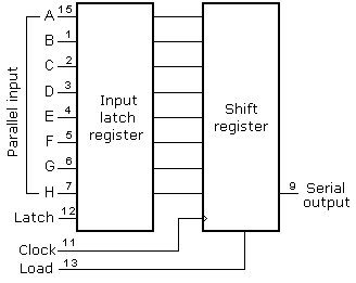
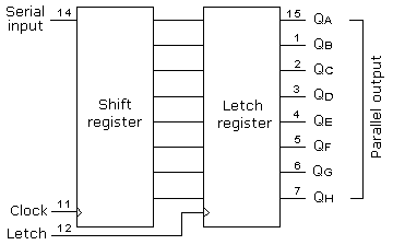
There are two types of shift registers: input and output. Input shift registers receive data in parallel, through 8 lines and then send it serially through two lines to a microcontroller. Output shift registers work in the opposite direction; they receive serial data and on a "latch" line signal, they turn it into parallel data. Shift registers are generally used to expand the number of input-output lines of a microcontroller. They are not so much in use any more though, because most modern microcontrollers have a large number of pins. However, their use with microcontrollers such as PIC16F84 is very important.
7.7.1 Input shift register 74HC597
Input shift registers transform parallel data into serial data and transfers it to a microcontroller. Their working is quite simple. There are four lines for the transfer of data: Clock, Latch, Load and Data. Data is first read from the input pins by an internal register through a 'latch' signal. Then, with a 'load' signal, data is transferred from the input latch register to the shift register, and from there it is serially transferred to a microcontroller via 'data' and 'clock' lines.

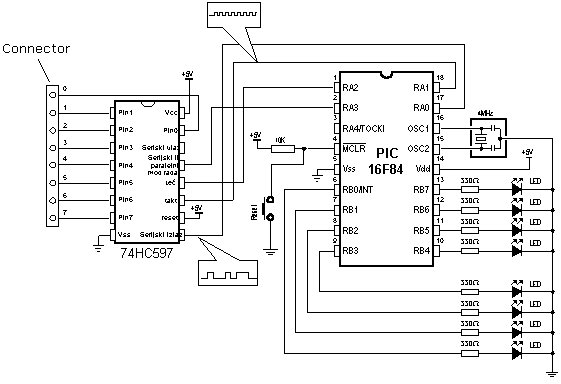
An outline of the connection of the shift register 74HC597 to a micro, is shown below.

In order to simplify the main program, a
macro can be used for the input shift register. Macro HC597 has two
parameters:
HC597 macro Var, Var1
Var variable where data from shift register input pins is transferred
Var1 loop counter
Example: HC597 data, counter
Data from the input pins of the shift register is stored in data variable. Timer/counter variable is used as a loop counter.
Macro listing:
HC597 MACRO    VAR,VARL
    LOCAL    LOOP                ;Local  label
            MOVLW .8            ;Transfer  eight bits
            MOVWF     VARL         ;initializing  counter

            BSF LATCH            ;Receive  pin states  into  input latch
            NOP
            BCF    LATCH

            BCF LOAD            ;Transfer  the  contents  of  input latch to
            NOP                 ;SHIFT reg.
            BSF    LOAD
LOOP
            RLF    VAR,F            ;Rotate  "Var"  one place  to  the  left
            BTFSS DATAA            ;Is  Data line  =  "1"   ?
            BCF VAR,0             ;If  not,   clear bit   '0'   in Var
            BTFSC DATAA         ;Is  Data line  =  "0"   ?
            BSF    VAR,0            ;If  not,   set bit   '0'

            BSF CLOCK            ;Generate  one  clock
            NOP
            BCF    CLOCK

            DECFSZ VARL,F        ;Has  8 bits been received  ?
            GOTO LOOP            ;If  not,   repeat
            ENDM
Example of how to use the HC597 macro is given in the following program. Program receives data from a parallel input of the shift register and moves it serially into the RX variable of the microcontroller. LEDs connected to port B will indicate the result of the data input.
PROCESSOR  16f84
#include "P16F84.inc"
__CONFIG _CP_0FF  &  _WDT_0FF  &  _PWRTE_0N  &  _XT_0SC

            CBLOCK    OXOC          ;RAM  starting address
            RX
            COUNTSPI
            ENDC

#DEFINE DATAA  PORTA,0             ;Any other  I/O pin could be used
#DEFINE CLOCK PORTA, 1
#DEFINE LATCH PORTA, 2
#DEFINE LOAD  PORTA,3


            ORG        0X00            ;Reset vector
            GOTO     MAIN
            ORG        0X04            ;Interrupt vector
            GOTO     MAIN             ;no  interrupt  routine

            #include  "hc597.inc"
MAIN                                ;Beginning of   the program
            BANKSEL TRISA
            MOVLW   B'00010001'     ;initializing port A
            MOVWF   TRISA             ;TRISA <-  0x11
            CLRF     TRISB             ;Pins  of  porta B   are  output
            BANKSEL  PORTA

            CLRF     PORTA            ;PORTA <-  0x00
            BSF        LOAD            ;Enable   SHIFT  register

LOOP
            HC597   RX,   COUNTSPI    ;States   of  input pins   of  SHIFT reg.
            MOVF     RX,W            ;are  stored in variable RX
            MOVWF    P0RTB            ;Set the   content of RX  reg.   to port B
            GOTO     LOOP             ;Repeat  the  loop
            END                     ;End of program
7.7.2 Output shift register

Output shift registers transform serial data into parallel data. On every rising edge of the clock, the shift register reads the value from data line, stores it in temporary register, and then repeats this cycle 8 times. On a signal from 'latch' line, data is copied from the shift register to input register, thus data is transformed from serial into parallel data.
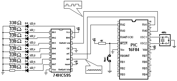
An outline of the 74HC595 shift register connections is shown on the diagram below:

Macro used in this example can be found
in hc595.inc file, and is called HC595.
Macro HC595 has two parameters:
HC595 macro Var, Var1
Var variable whose contents is transferred to outputs of shift
register.
Var1 loop counter
Example: HC595 Data, counter
The data we want to transfer is stored in data variable, and counter
variable is used as a loop counter.
HC595 MACRO VAR,VARL
    LOCAL LOOP                    ;Local  label
            MOVLW .8             ;Transfer  eight bits
            MOVWF VARL            ;Initialising  counter


            RLF    VAR,F            ;Rotate "Var" on place to the  left

            BTFSS STATUS,C         ;Is  carry =  "1"   ?
            BCF DATAA            ;If not,   set Dataa line   to  "0"
            BTFSC STATUS,C        ;Is  carry =  "0"   ?
            BSF    DATAA            ;If not,   set Dataa line   to  "1"

            BSF CLOCK            ;Generate  one   clock
            NOP
            BCF CLOCK

            DECFSZ VARL,F        ;Has  eight bits been sent  ?
            GOTO LOOP              ;If not,   repeat

            BSF LATCH            ;If  all  8 bits have been sent,
            NOP                    ;contents  of  SHIFT register  to    send the output latch
            BCF     LATCH
            ENDM
An example of how to use the HC595 macro is given in the following program. Data from variable TX is serially transferred to shift register. LEDs connected to the parallel output of the shift register will indicate the state of the lines. In this example value 0xCB (1100 1011) is sent so that the seventh, sixth, third, first, and zero LEDs are illuminated.
			PROCESSOR  16f84
			#include "pl6f84.inc"
__CONFIG _CP_0FF  &  _TODT_0FF   &  _PWRTE_0N  &   _XT_0SC

			CBLOCK 0X0C				;RAM  starting address
			TX						;Belongs   to  the  function "HC595"
			COUNTSPI
			ENDC

#DEFINE DATAA PORTA, 0
#DEFINE CLOCK PORTA, 1
#DEFINE LATCH PORTA,2


			ORG  0X00				;Reset vector
			GOTO MAIN
			ORG 0X04				;Interrupt vector
			GOTO MAIN				;no   interrupt routine

			INCLUDE "HC595.INC"

MAIN								;Beginning of  the program
			BANKSEL TRISA
			MOVLW  B'00011000'		;Initialising  port A
			MOVWF TRISA  			;TRISA <-  0x18
			BANKSEL PORTA
			CLRF PORTA 				;PORTA <-  0x00
			MOVLW 0XCB				;Fill TX buffer
			MOVWF TX 				;TX <-   '11001011'
			HC595 TX, COUNTSPI
LOOP
     		GOTO     LOOP			;Remain  at this  line
			END						;End of program
User Comments
No Posts found !Login to Post a Comment.