Introduction to microcontrollers
A micro-controller can be compared to a small stand alone computer, it is a very powerful device, which is capable of executing a series of pre-programmed tasks and interacting with other hardware devices. Being packed in a tiny integrated circuit (IC) whose size and weight is usually negligible, it is becoming the perfect controller for robots or any machines requiring some kind of intelligent automation. A single microcontroller can be sufficient to control a small mobile robot, an automatic washer machine or a security system. Any microcontroller contains a memory to store the program to be executed, and a number of input/output lines that can be used to interact with other devices, like reading the state of a sensor or controlling a motor.
Nowadays, microcontrollers are so cheap and easily available that it is common to use them instead of simple logic circuits like counters for the sole purpose of gaining some design flexibility and saving some space. Some machines and robots will even rely on a multitude of microcontrollers, each one dedicated to a certain task. Most recent microcontrollers are 'In System Programmable', meaning that you can modify the program being executed, without removing the microcontroller from its place.
Today, microcontrollers are an indispensable tool for the robotics hobbyist as well as for the engineer. Starting in this field can be a little difficult, because you usually can't understand how everything works inside that integrated circuit, so you have to study the system gradually, a small part at a time, until you can figure out the whole image and understand how the system works.
The 8051 microcontroller architecture
The 8051 is the name of a big family of microcontrollers. The device which we are going to use along this tutorial is the 'AT89S52' which is a typical 8051 microcontroller manufactured by Atmel™. Note that this part doesn't aim to explain the functioning of the different components of a 89S52 microcontroller, but rather to give you a general idea of the organization of the chip and the available features, which shall be explained in detail along this tutorial.
The block diagram provided by Atmel™ in their datasheet showing the architecture the 89S52 device can seem very complicated, and since we are going to use the C high level language to program it, a simpler architecture can be represented as the figure 1.2.A.
This figures shows the main features and components that the designer can interact with. You can notice that the 89S52 has 4 different ports, each one having 8 Input/output lines providing a total of 32 I/O lines. Those ports can be used to output DATA and orders do other devices, or to read the state of a sensor, or a switch. Most of the ports of the 89S52 have 'dual function' meaning that they can be used for two different functions: the fist one is to perform input/output operations and the second one is used to implement special features of the microcontroller like counting external pulses, interrupting the execution of the program according to external events, performing serial data transfer or connecting the chip to a computer to update the software.
Each port has 8 pins, and will be treated from the software point of view as an 8-bit variable called 'register', each bit being connected to a different Input/Output pin.
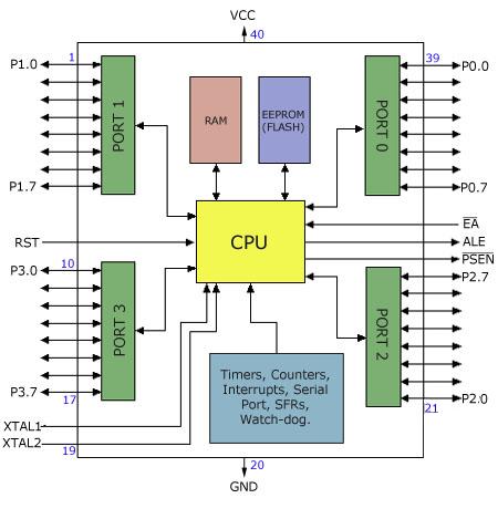
Figure 1.2.A
You can also notice two different memory types: RAM and
EEPROM. Shortly, RAM is used to store variable during
program execution, while the EEPROM memory is used to
store the program itself, that's why it is often referred
to as the 'program memory'. The memory organization will
be discussed in detail later.
The special features of the 89S52 microcontroller are
grouped in the blue box at the bottom of figure 1.2.A.
At this stage of the tutorial, it is just important to
note that the 89S52 incorporates hardware circuits that
can be used to prevent the processor from executing various
repetitive tasks and save processing power for more complex
calculations. Those simple tasks can be counting the number
of external pulses on a pin, or generating precise timing
sequences.
It is clear that the CPU (Central Processing Unit) is the heart
of the microcontrollers, It is the CPU that will Read the program
from the FLASH memory and execute it by interacting with the different
peripherals discussed above.
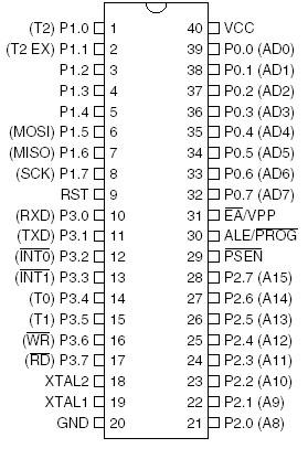
Figure 1.2.B
Figure 1.2.B shows the pin configuration of the 89S52, where the function of each pin is written next to it, and, if it exists, the dual function is written between brackets. The pins are written in the same order as in the block diagram of figure 1.2.A, except for the VCC and GND pins which I usually note at the top and the bottom of any device.
Note that the pin that have dual functions, can still be used normally as an input/output pin. Unless you program uses their dual functions, All the 32 I/O pins of the microcontroller are configured as input/output pins.
Most of the function of the pins of the 89S52 microcontroller will be discussed in detail, except for the pins required to control an external memory, which are the pins number 29, 30 and 31. Since we are not going to use any external memory, pins 29 and 30 will be ignored through all the tutorial, and pin 31 (EA) always connected to VCC (5 Volts) to enable the micro-controller to use the internal on chip memory rather than an external one (connecting the pin 31 to ground would indicate to the microcontroller that an external memory is to be used instead of the internal one).
User Comments
No Posts found !Login to Post a Comment.