LCD Display
More microcontroller devices are using 'smart LCD' displays to output visual information. The following discussion covers the connection of a Hitachi LCD display to a PIC microcontroller. LCD displays designed around Hitachi's LCD HD44780 module, are inexpensive, easy to use, and it is even possible to produce a readout using the 8 x 80 pixels of the display. Hitachi LCD displays have a standard ASCII set of characters plus Japanese, Greek and mathematical symbols.
 A 16x2 line Hitachi HD44780 display
For a 8-bit data bus, the display requires a +5V supply plus 11 I/O lines.
For a 4-bit data bus it only requires the supply lines plus seven extra
lines. When the LCD display is not enabled, data lines are tri-state which
means they are in a state of high impendance (as though they are
disconnected) and this means they do not interfere with the operation of
the microcontroller when the display is not being addressed.
The LCD also requires 3 "control" lines from the microcontroller.
| Enable (E) | This line allows access to the display through R/W and RS lines. When this line is low, the LCD is disabled and ignores signals from R/W and RS. When (E) line is high, the LCD checks the state of the two control lines and responds accordingly. |
| Read/Write (R/W) | This line determines the direction of data between the LCD and microcontroller. When it is low, data is written to the LCD. When it is high, data is read from the LCD. |
| Register select (RS) | With the help of this line, the LCD interprets the type of data on data lines. When it is low, an instruction is being written to the LCD. When it is high, a character is being written to the LCD. |
Logic status on control lines:
E 0 Access to LCD disabled
1 Access to LCD enabled
R/W 0 Writing data to LCD
1 Reading data from LCD
RS 0 Instruction
1 Character
Pin assignment
The pin assignment shown in Table 1. is the industry standard for character LCD-modules with a maximum of 80 characters.To be sure always check the manufacturers datasheet!
To locate pin 1 on a module check the manufacturers datasheet!
| Pin number | Symbol | Level | I/O | Function |
|---|---|---|---|---|
| 1 | Vss | - | - | Power supply (GND) |
| 2 | Vcc | - | - | Power supply (+5V) |
| 3 | Vee | - | - | Contrast adjust |
| 4 | RS | 0/1 | I | 0 = Instruction input 1 = Data input |
| 5 | R/W | 0/1 | I | 0 = Write to LCD module 1 = Read from LCD module |
| 6 | E | 1, 1-->0 | I | Enable signal |
| 7 | DB0 | 0/1 | I/O | Data bus line 0 (LSB) |
| 8 | DB1 | 0/1 | I/O | Data bus line 1 |
| 9 | DB2 | 0/1 | I/O | Data bus line 2 |
| 10 | DB3 | 0/1 | I/O | Data bus line 3 |
| 11 | DB4 | 0/1 | I/O | Data bus line 4 |
| 12 | DB5 | 0/1 | I/O | Data bus line 5 |
| 13 | DB6 | 0/1 | I/O | Data bus line 6 |
| 14 | DB7 | 0/1 | I/O | Data bus line 7 (MSB) |
| 15 | LED + | - | - | LED + |
| 16 | LED - | - | - | LED - |
Instruction set
| Instruction | Code | Description | Execution time** | |||||||||
|---|---|---|---|---|---|---|---|---|---|---|---|---|
| RS | R/W | DB7 | DB6 | DB5 | DB4 | DB3 | DB2 | DB1 | DB0 | |||
| Clear display | 0 | 0 | 0 | 0 | 0 | 0 | 0 | 0 | 0 | 1 | Clears display and returns cursor to the home position (address 0). | 1.64mS |
| Cursor home | 0 | 0 | 0 | 0 | 0 | 0 | 0 | 0 | 1 | * | Returns cursor to home position (address 0). Also returns display being shifted to the original position. DDRAM contents remains unchanged. | 1.64mS |
| Entry mode set | 0 | 0 | 0 | 0 | 0 | 0 | 0 | 1 | I/D | S | Sets cursor move direction (I/D), specifies to shift the display (S). These operations are performed during data read/write. | 40uS |
| Display On/Off control | 0 | 0 | 0 | 0 | 0 | 0 | 1 | D | C | B | Sets On/Off of all display (D), cursor On/Off (C) and blink of cursor position character (B). | 40uS |
| Cursor/display shift | 0 | 0 | 0 | 0 | 0 | 1 | S/C | R/L | * | * | Sets cursor-move or display-shift (S/C), shift direction (R/L). DDRAM contents remains unchanged. | 40uS |
| Function set | 0 | 0 | 0 | 0 | 1 | DL | N | F | * | * | Sets interface data length (DL), number of display line (N) and character font(F). | 40uS |
| Set CGRAM address | 0 | 0 | 0 | 1 | CGRAM address | Sets the CGRAM address. CGRAM data is sent and received after this setting. | 40uS | |||||
| Set DDRAM address | 0 | 0 | 1 | DDRAM address | Sets the DDRAM address. DDRAM data is sent and received after this setting. | 40uS | ||||||
| Read busy-flag and address counter | 0 | 1 | BF | CGRAM / DDRAM address | Reads Busy-flag (BF) indicating internal operation is being performed and reads CGRAM or DDRAM address counter contents (depending on previous instruction). | 0uS | ||||||
| Write to CGRAM or DDRAM | 1 | 0 | write data | Writes data to CGRAM or DDRAM. | 40uS | |||||||
| Read from CGRAM or DDRAM | 1 | 1 | read data | Reads data from CGRAM or DDRAM. | 40uS | |||||||
- DDRAM = Display Data RAM.
- CGRAM = Character Generator RAM.
- DDRAM address corresponds to cursor position.
- * = Don't care.
- ** = Based on Fosc = 250KHz.
| Bit name | Settings | |
|---|---|---|
| I/D | 0 = Decrement cursor position | 1 = Increment cursor position |
| S | 0 = No display shift | 1 = Display shift |
| D | 0 = Display off | 1 = Display on |
| C | 0 = Cursor off | 1 = Cursor on |
| B | 0 = Cursor blink off | 1 = Cursor blink on |
| S/C | 0 = Move cursor | 1 = Shift display |
| R/L | 0 = Shift left | 1 = Shift right |
| DL | 0 = 4-bit interface | 1 = 8-bit interface |
| N | 0 = 1/8 or 1/11 Duty (1 line) | 1 = 1/16 Duty (2 lines) |
| F | 0 = 5x7 dots | 1 = 5x10 dots |
| BF | 0 = Can accept instruction | 1 = Internal operation in progress |
1-line displays
Shown after reset (with N=0).| Display size | Visible | |
|---|---|---|
| Character positions | DDRAM addresses | |
| 1*8 | 00..07 | 00h..07h |
| 1*16 | 00..15 [1] [2] [3] | 00h..0Fh |
| 1*20 | 00..19 | 00h..13h |
| 1*24 | 00..23 | 00h..17h |
| 1*32 | 00..31 | 00h..1Fh |
| 1*40 | 00..39 | 00h..27h |
2-line displays
Shown after reset (with N=1).| Display size | Visible | |
|---|---|---|
| Character positions | DDRAM addresses | |
| 2*16 | 00..15 [1] | 00h..0Fh + 40h..4Fh |
| 2*20 | 00..19 | 00h..13h + 40h..53h |
| 2*24 | 00..23 | 00h..17h + 40h..57h |
| 2*32 | 00..31 | 00h..1Fh + 40h..5Fh |
| 2*40 | 00..39 | 00h..27h + 40h..67h |
According to their datasheets DDRAM addresses 80h..8Fh + C0h..CFh are used.
Make/model: Emerging Display Technologies/ EW162G0YMY
Make/model: Mitsutech EW162G0YMY
4-line displays
Shown after reset (with N=1).| Display size | Visible | |
|---|---|---|
| Character positions | DDRAM addresses | |
| 4*16 | 00..15 [1] [2] | 00h..0Fh + 40h..4Fh + 14h..23h + 54h..63h |
| 4*20 | 00..19 | 00h..13h + 40h..53h + 14h..27h + 54h..67h |
| 4*40 | (00..39) on 1st controller and (00..39) on 2nd |
(00h..27h + 40h..67h) on 1st controller and (00h..27h + 40h..67h) on 2nd |
Found DDRAM addresses 00h..0Fh + 40h..4Fh + 10h..1Fh + 50h..5Fh to be functional for a 4*16 display size.
Make/model: Optrex / DMC16433.
[2] Tushar Rane:
Found DDRAM addresses 00h..0Fh + 40h..4Fh + 10h..1Fh + 50h..5Fh to be functional for a 4*16 display size.
Make/model: not mentioned / not mentioned.
Interfacing
8-bit interface
Example of busy flag testing using an 8-bit interface.
4-bit interface
Example of busy flag testing using a 4-bit interface.
Character set
Characterset for 5x7 dot font (to be completed..)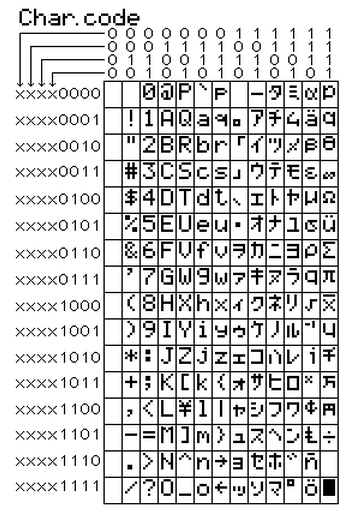
Writing data to the LCD is done in several steps
:Set R/W bit to low
Set RS bit to logic 0 or 1 (instruction or character)
Set data to data lines (if it is writing)
Set E line to high
Set E line to low
Read data from data lines (if it is reading)
Reading data from the LCD is done in the same way, but control line R/W has to be high. When we send a high to the LCD, it will reset and wait for instructions. Typical instructions sent to LCD display after a reset are: turning on a display, turning on a cursor and writing characters from left to right. When the LCD is initialized, it is ready to continue receiving data or instructions. If it receives a character, it will write it on the display and move the cursor one space to the right. The Cursor marks the next location where a character will be written. When we want to write a string of characters, first we need to set up the starting address, and then send one character at a time. Characters that can be shown on the display are stored in data display (DD) RAM. The size of DDRAM is 80 bytes.
The LCD display also possesses 64 bytes of Character-Generator (CG) RAM. This memory is used for characters defined by the user. Data in CG RAM is represented as an 8-bit character bit-map. Each character takes up 8 bytes of CG RAM, so the total number of characters, which the user can define is eight. In order to read in the character bit-map to the LCD display, we must first set the CG RAM address to starting point (usually 0), and then write data to the display. The definition of a 'special' character is given in the picture.
Before we access DD RAM after defining a special character, the program must set the DD RAM address. Writing and reading data from any LCD memory is done from the last address which was set up using set-address instruction. Once the address of DD RAM is set, a new written character will be displayed at the appropriate place on the screen. Until now we discussed the operation of writing and reading to an LCD as if it were an ordinary memory. But this is not so. The LCD controller needs 40 to 120 microseconds (uS) for writing and reading. Other operations can take up to 5 mS. During that time, the microcontroller can not access the LCD, so a program needs to know when the LCD is busy. We can solve this in two ways.
One way is to check the BUSY bit found on
data line D7. This is not the best method because LCD's can get stuck, and
program will then stay forever in a loop checking the BUSY bit. The other
way is to introduce a delay in the program. The delay has to be long
enough for the LCD to finish the operation in process. Instructions for
writing to and reading from an LCD memory are shown in the previous table.
At the beginning we mentioned that we needed 11 I/O lines to communicate
with an LCD. However, we can communicate with an LCD through a 4-bit data
bus. Thus we can reduce the total number of communication lines to seven.
The wiring for connection via a 4-bit data bus is shown in the diagram
below. In this example we use an LCD display with 2x16 characters,
labeled LM16X212 by Japanese maker SHARP. The message 'character' is
written in the first row: and two special characters '~' and '}' are
displayed. In the second row we have produced the word ' Romux '.
Connecting an LCD display to a microcontroller
File lcd.inc contains a group of macros for use when working with LCD displays.
CONSTANT FUNCTSET8 = b'00110000'         ; 8-bit mode, 2 lines
CONSTANT FUNCTSET4 = b'00100000'         ; 4-bit mode, 2 lines
CONSTANT DDZERO  = b'10000000'          ;  Write  0  to DDRAH
CONSTANT LCD2L  =  b'00101000'
CONSTANT LCDCONT  =  b'00001100'
CONSTANT LCDSH = b'00101000'
;Commands  for working with LCD display
CONSTANT     LCDCLR =      b'00000001'        ;clear  display,   cursor home
CONSTANT     LCDCH     =      b'00000010'        ;cursor home
CONSTANT     LCDCL     =     b'00000100'        ;move  cursor  to  the  left
CONSTANT     LCDCR    =     b'00000110'        ;move  cursor  to  the  right
CONSTANT     LCDSL     =     b'00011000'        ;move  the  content of  display
                                        ;to  the  left
CONSTANT     LCDSR    =     b'00011100'        ;move  the  content of  display
                                        ;to  the  right
CONSTANT     LCDL1    =     b'10000000'        ;select line  1
CONSTANT     LCDL2     =     b'11000000'        ;select line  2


LCDINIT MACRO
            BANK1
            CLRF    LCDDSPORT            ;LCDdsport where  LCD  is  an output
            BANKO
            CALL    DELAY1MS
            CALL    DELAY1MS
            CALL    DELAY1MS
            CALL    DELAY1MS             ;4 ms pause
            MOVLW    FUNCTSET8            ;Begin initialization in
            CALL    SENDW                ;8-bit mode
            CALL    DELAY1MS
            CALL    DELAY1MS            ;2 ms  pause
            MOVLW    DDZERO                ;Write  0  to DDRAM
            CALL    SENDW

            MOVLW  FUNCTSET4            ;From this   line,   LCD works  in 4-bit mode
            CALL   SENDW

;Commands   for  initializing LCD
            LCDCMD    LCD2L
            LCDCMD    LCDC0NT
            LCDCMD    LCDSH                ;lcd has  2  lines
            LCDCMD    LCDCLR            ;Clear  LCD

            ENDM

LCDCMD    MACRO    LCDCOMMAND
            MOVLW LCDCOMMAND
            CALL LCDCOMD
            ENDM

LCDCLR    MACRO
            MOVLW    LCDCLR
            CALL LCDCOMD
            ENDM

LCD_DDADR MACRO        DDRAMADDRESS
    LOCAL    VALUE   =    DDRAMADDEESS | 0x80;DDRAH  starting address
            MOVLW    VALUE
            CALL LCDCOMD
            ENDM

LCDCOMD
            CLRF    LCDBUF
            GOTO    LCDWR
LCDDATA
            CLRF    LCDBUF
            BSF    LCDBUF ,RS
LCDWR
            MOVWF    LCDTEMP
            ANDLW    B'11110000'
            IORWF    LCDBUF ,W
            CALL    SENDW
            SWAPF    LCDTEMP,W
            ANDLW    B'11110000'
            IORWF    LCDBUF,W
            CALL SENDW
            RETURN
;Prints   the  content of  register W on LCD
SENDW
            CLRF    LCDDSPORT
            MOVWF    LCDDSPORT
            CALL    DELAY1MS
            BSF    LCDDSPORT,EN
            BCF    LCDDSPORT,EN
            CALL    DELAY1MS
            CLRF LCDDSPORT
            RETURN


ICDTEXT MACRO SELECT,   TEXT
;This macro prints  text parameter  of up   to
;16  characters  from the  current cursor
; position

    LOCAL    MESSAGE
    LOCAL    START
    LOCAL    EXIT
    LOCAL    I=0
            GOTO  START
PORUKA       DT   TEXT                ;Form a lookup  table  from parameters
            DT  0
START
            IF SELECT==1
            LCDCMD LCDL1
            ELSE
            IF SELECT==2
            LCDCMD LCDL2
            ENDIF
            ENDIF
WHILE    I<16                        ;Conditional   program translation -  repeat 16x
            CALL   HESSAGE+I        ;Read lookup  table  and store value   to W
            ADDLW .0
            BZ  EXIT                ;until  it reads   zero
            CALL LCDDATA            ;Call  the  routine  that prints W on LCD
            I=I+1
        ENDW
        EXIT
        ENDM


LEDBYTE MACRO ARGO
            DIGBYTE  ARGO            ;Hundreds  digit  is  in Digl,   tens  digit in Dig2
                                    ;and ones  digit is  in Dig3
            MOVF    DIG1,W
            BTFSC  STATUS,Z         ;If  zero,  move  the  cursor
            MOVLW 0XFO                 ;If not zero,  print the hundreds  digit
            ADDLW 0X30
            CALL  LCDDATA

            MOVF    DIG2,W             ;If  zero,  move  the  cursor
            BTFSC  STATUS,Z         ;If not zero,  print the hundreds  digit
            MOVLW OXFO
            ADDLW 0X30
            CALL     LCDDATA

            MOVF    DIG3,W
            ADDLW 0X30
            CALL     LCDDATA
            ENDM


DELAY1MS                            ;lms PAUSE
            MOVLW    .100
            MOVWF    LOOPCNT
DELAYLOUS
            NOP        ;lus
            NOP        ;lus
            NOP        ;lus
            NOP        ;lus
            NOP        ;lus
            NOP        ;lus
            NOP        ;lus
            DECFSZ    LOOPCNT,F    ;lus
            GOTO DELAYL10US    ;2us
            RETURN
Using the macro for LCD support
| lcdinit | Macro used to initialize port connected to LCD. LCD is configured to work in 4-bit mode. | ||
| Example: | lcdinit | ||
| lcdtext | lcdtext prints the text of up to 16 characters, which is specified as a macro parameter. First parameter selects the line in which to start printing. If select is zero, text is printed from the current cursor position. | ||
| Example: | lcdtext 1, " Romux " | ||
| lcdtext 1, "Temperature1" ;Print the text starting from line 1, character 1 | |||
| lcdtext 2, "temp=" ;Print the text starting from line 2, character 1 | |||
| lcdtext 0, " C" ;Print C in the rest of the line 2 | |||
| lcdcmd | Sends command instructions | ||
| LCDCLR | = b'00000001' | ;Clear display, cursor home | |
| LCDCH | = b'00000010' | ;Cursor home | |
| LCDCL | = b'00000100' | ;Move the cursor to the left | |
| LCDCR | = b'00000110' | ;Move the cursor to the right | |
| LCDSL | = b'00011000' | ;Move the content of display to the left | |
| LCDSR | = b'00011100' | ;Move the content of display to the right | |
| LCDL1 | = b'10000000' | ;Select line 1 | |
| LCDL2 | = b'11000000' | ;Select line 2 | |
| Example: | lcdcmd LCDCH | ||
| lcdbyte | Prints one byte variable and omits leading zeros | ||
| Example: | lcdbyte Temperature | ||
When working with a microcontroller the numbers are presented in a binary form. As such, they cannot be displayed on a display. That's why it is necessary to change the numbers from a binary system into a decimal system so they can be easily understood. For printing the variables lcdbyte and lcdword we have used the macros digbyte and digword which convert the numbers from binary system into a decimal system and print the result on LCD. Main program has the purpose of demonstrating use of LCD display. At the start it's necessary to declare variables LCDbuf, LCDtemp, Digtemp, Dig1, Dig2, and Dig3 used by the macros for LCD support. It is also necessary to state the port of microcontroller that LCD is connected to. Program initializes the LCD and demonstrates printing text and 8-bit variable temp.
        PROCESSOR  16F84
        #INCLUDE "P16F84.INC"
        __CONFIG _CP_0FF  &  _WDT_0FF  &  _PWRTE_0N  &  _XT_0SC

        CBLOCK 0X0C                ;RAM  starting address
        HICNT
        LOCNT
        LOOPCNT                     ;Belongs  to macro  "pausems"
        LCDBUF
         LCDTEMP                    ;Belongs  to  funkctions  "LCDxxx"
        DIGTEMP
        DIGL
        DIG2
        DIG3                     ;Belongs  to macro  "digbyte"
        TEMP
        ENDC

        ORG 0X00                 ;Reset vector
        GOTO MAIN
        ORG 0X04                ;Intertupt vector
        GOTO MAIN                ;no  interrupt routine

        #INCLUDE "ROMUX_LIB.INC"
        #INCLUDE "LED.INC"

LCDDSPORT EQU P0RTB                ;LCD  IS  ON PORT B(4 DATA LINES  ON RB4-RB7)
RS  EQU    1                     ;RS  LINE RB1
RW EQU    2                     ;RW LINE RB2
EN EQU    3                         ;EN LINE RB3


MAIN
            MOVLW  .23
            MOVWF   TEMP        ;Put any value   to variable  temp ; for printing on LCD

            LCDINIT                ;Incitializing LCD
LOOP
            LCDCMD 0X01            ;Clear  LCD
            LCDTEXT 1,"   ROMUX   ";Print text from line  1,   char  1
            LCDTEXT 2,"PROBA LCD";Print text from line  2,   char  1
            PAUSEMS .2000         ;2  sec pause
            LCDCMD 0X01            ;Clear  LCD
            LCDTEXT 1,"TEMPERATURE" ;Print text from line  1,   char  1
            LCDTEXT 2,"TEMP="    ;Print text from line  2,   char  1
            LCDBYTE TEMP        ;Print decimal value  of variable
            LCDTEXT 0,"C"        ;Print text from the  current
            PAUSEMS    .2000          ;cursor position

              GOTO  LOOP
            END
User Comments
No Posts found !Login to Post a Comment.
Found DDRAM addresses 00h..07h + 40h..47h to be functional for a 1*16 display size.
Make/model: not mentioned / SC1601AS*B.
[2] Hendrik Abma:
Found DDRAM addresses 00h..07h + 40h..47h to be functional for a 1*16 display size.
Make/model: Samtron / KP-03.
[3] Luigi Candurro:
Found DDRAM addresses 00h..07h + 40h..47h to be functional for a 1*16 display size.
CMC116-01.