MPSIM Simulator
Simulator is part of the MPLAB environment which provides a better insight into the workings of a microcontroller. Through a simulator, we can monitor current variable values, register values and status of port pins. Truthfully, simulator does not have the same value in all programs. If a program is simple (like the one given here as an example), simulation is not of great importance because setting port B pins to logic one is not a difficult task. However, simulator can be of great help with more complicated programs which include timers, different conditions where something happens and other similar requirements (especially with mathematical operations). Simulation, as the name indicates "simulates the work of a microcontroller". As microcontroller executes instructions one by one, simulator is conceived - programmer moves through a program step-by-step (line-by-line) and follows what goes on with data within the microcontroller. When writing is completed, it is a good trait for a programmer to first test his program in a simulator, and then run it in a real situation. Unfortunately, as with many other good habits, man tends to avoid this one too, more or less. Reasons for this are partly personality, and partly a lack of good simulators.

Starting the program simulation
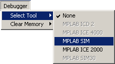
Simulator is activated by clicking on DEBUGGER > SELECT TOOL > MPLAB SIM, as shown in the image above. Four new icons appear to the right. They are related to simulator only, and have the following meaning:
|
|
Start the program execution at full speed. When started, simulator executes the program until "paused" by the icon below (just as with cassette or CD player). |
|
|
Stops full-speed program execution. After this icon has been clicked, program execution may be continued step-by-step or at full-speed. |
|
|
Step Into icon. Step-by-step program execution. Clicking on this icon executes the succeeding program line. It enters the macros and subroutines. |
|
|
Same as the previous icon, except it does not enter the macros and subroutines. |
|
|
Resets the microcontroller. Clicking on this icon positions the program counter to the beginning of program and simulation may begin. |
First thing we need to do, as in a real situation, is to reset a microcontroller with DEBUGGER > RESET command
or by clicking on the reset icon. This command results in green marker line positioned at the beginning of
the program, and program counter PCL is positioned at zero which can also be seen in
Special Functions Registers window.

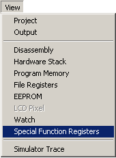
One of the main simulator features is the ability to view register status within a microcontroller. These registers are also called special function registers, or SFR registers. We can get a window with SFR registers by clicking on
VIEW > SPECIAL FUNCTION REGISTERS.
Beside SFR registers, it is useful to have an insight into file registers. Window with file registers can be opened by clicking on
VIEW > FILE REGISTERS.
If there are variables in the program, it is good to monitor them, too. Each variable is assigned one window (Watch Windows) by clicking on VIEW > WATCH.

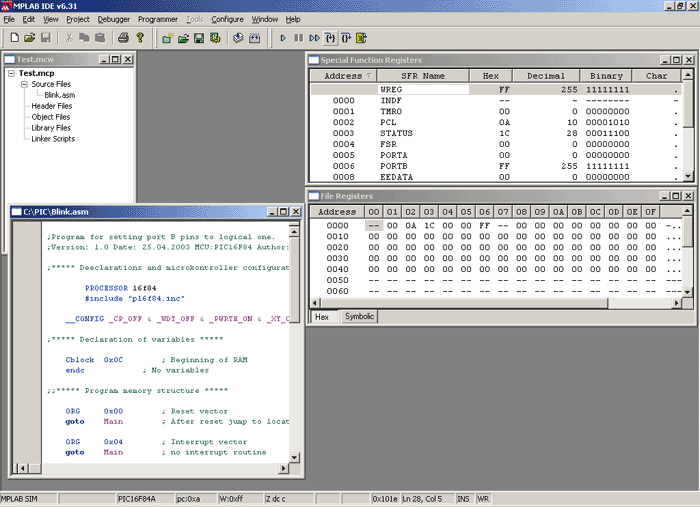
Simulator with open SFR registers and File registers windows
When all the variables and registers of interest are placed on the simulator working area, simulation may begin. Next command can be either Step Into or Step Over, as we may want to go into subroutines or not. Same commands can be issued via keyboard, by clicking F7 or F8.
In the SFR registers window, we can observe how register W receives value 0xFF and delivers it to port B.
By clicking on F7 key again, we don't achieve anything because program has arrived to an "infinite loop". Infinite loop is a term we will meet often. It represents a loop from which a microcontroller cannot get out until interrupt takes place (if it is used in a program), or until a microcontroller is reset.
User Comments
No Posts found !Login to Post a Comment.